I2C Driver
This driver has been released under the Eclipse Public License version 2.0! It can be found on GitHub.
The ASH WARE I2C eTPU Driver allows the Freescale eTPU to be connected to an I2C bus running in Standard-mode or Fast-mode, as either a master or slave node. By using the output pin pad open drain capability, no external hardware is required for this connection other than a pullup. This driver has been written to support both the eTPU and eTPU2 devices, and can run on any Freescale or STMicro chip with the eTPU/eTPU2 peripheral.
Versions
2.00 - modernize the host API and structure and move to GitHub
1.11 - fix minor scripting issues
1.10 - modified to run under DevTool (the new IDE)
1.00 - initial version
I2C Master Features and Details
The I2C master driver supports the following features.
- up to 400 KHz operation, or better. The actual limit depends upon the eTPU clock rate and other functions in the eTPU.
- read, write and combined format transfers
- 7-bit addressing
- START byte via combined format
- unexpected NACKs reported
- clock stretching (synchronization) by slave devices
- interrupt on transfer completion
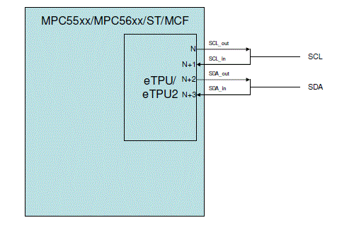
Arbitration (multi-master), high-speed mode, CBUS and 10-bit addressing are not currently supported. The I2C master solution uses 4 consecutive eTPU channels and their associated pins. The first two must be connected to the SCL wire, the second two to the SDA wire. They function as follows:
base channel: SCL_out
base channel+1: SCL_in
base channel+2: SDA_out
base channel+3: SDA_in

I2C Slave Features and Details
The I2C slave driver supports the following features.
- up to 400 KHz operation, or better. The actual limit depends upon the eTPU clock rate and other functions in the eTPU.
- programmable 7-bit address
- read, write and combined format transfers
- programmable acceptance of general calls
- handles START bytes
- interrupt on read request and transfer completion
- supports a wait-for-read-data mode wherein the slave driver holds the SCL wire low when a read request is received until the host has filled the read data buffer and alerted that eTPU that the data is ready.
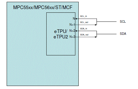
The I2C slave solution uses 4 consecutive eTPU channels and their associated pins. The first two must be connected to the SCL wire, the second two to the SDA wire. They function as follows:
base channel: SCL_in
base channel+1: SCL_out
base channel+2: SDA_in
base channel+3: SDA_out

Example Waveforms
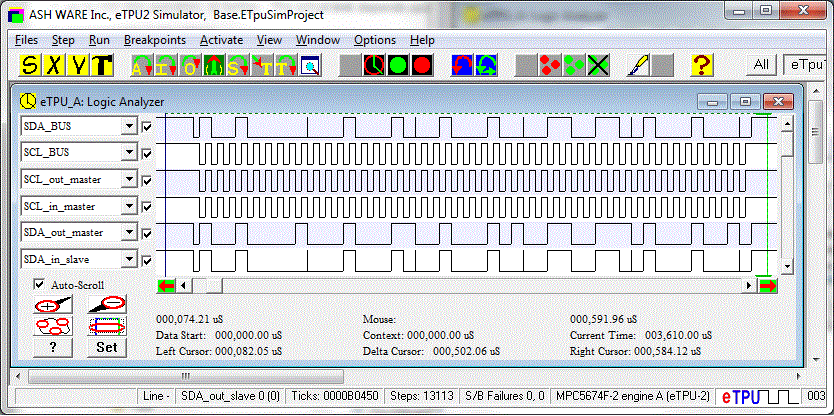
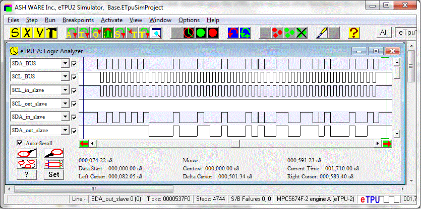
The following waveforms show the SCL and SDA wires during a write and read transfer. Both a master and slave have been instantiated on a single eTPU, and connected together. Signal levels for all the master channels (write transfer), and all the slave channels (read transfer) are shown as well.


Testing
Testing includes 100 % code and jump coverage of the eTPU software. All features described in the User Manual have been tested.
Project Artifacts
- User Manual
- I2C eTPU C source code files etec_i2c_master.[c,h] and etec_i2c_slave.[c,h] that implement the I2C driver functionality in the eTPU. These are configured for use with the ETEC eTPU C Compiler, but can be configured to work with other compilers if necessary (ETEC yields the best performance).
- eTPU Simulator test suite that tests all I2C master and slave features with 100% code and jump coverage.
- Host-side I2C driver software that initializes and works with the eTPU. This can be used as-is or modified for specific application requirements.
- Test / example host-side application software.
- eTPU System Simulator test suite for the I2C host software.

